Product Description
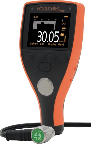
The Elcometer MTG8 Ultrasonic Material Thickness Gauge is the top of the range gauge with all the features and functionality necessary for measuring material thickness and velocity on virtually any material and for a wide range of applications.
As well as all the features of the MTG2, MTG4 and MTG6, the MTG8 allows users to store into memory up to three calibrations. Once saved the user can select a calibration memory without the need to re-calibrate the gauge, ideal for users who are measuring a variety of materials or thicknesses. Using the gauge’s alpha-numeric function, calibration memories can be re-named to suit the calibration setting.
Statistics
The MTG8 has user definable upper and lower limits with audible and visual pass/fail warnings. Limits can be set for individual readings or for each batch. If a measurement is taken which falls outside set limits, the reading value and the limit icon turn red, the red LED flashes and the alarm beeps providing immediate indication of problem areas.
Display Mode
The MTG8 has Differential Mode; once a user defined nominal thickness value is set, the gauge displays the measured thickness together with the variation from the set nominal value thus indicating areas of the material which are thinner or thicker than expected.
The MTG8 offers B-Scan, a time based, cross sectional 2 dimensional graphical view of the material under test, ideal for relative depth analysis. The zoom of the B-Scan reading can either be set to automatic or can be defined by the user to focus on areas of interest.
Data Logging
The MTG8 can store 100,000 readings in up to 1,000 sequential or grid type batches. Using grid batching, readings are stored in a spreadsheet type format. The Obst feature, allows the user to record an obstruction within the grid.
Data Output
Compatible with ElcoMaster®, PC & Mobile App, readings can be downloaded via USB or Bluetooth® to PC, iOS or Android™ devices for further analysis and reporting.
Product Features
Elcometer MTG8 Ultrasonic Material Thickness Gauge
|  |
Specifications
| MTG2 | MTG4 | MTG6 | MTG8 | ||
| Easy to use menu structure in multiple languages | ● | ● | ● | ● | |
| Tough, impact, waterproof and dust resistant – equal to IP54 | ● | ● | ● | ● | |
| Bright colour screen with permanent backlight | ● | ● | ● | ● | |
| Ambient light sensor, with adjustable brightness | ● | ● | ● | ● | |
| Scratch and solvent resistant display; 2.4″ (6cm) TFT | ● | ● | ● | ● | |
| Large positive feedback buttons | ● | ● | ● | ● | |
| USB power supply via PC | ● | ● | ● | ● | |
| Low battery indicator | ● | ● | ● | ● | |
| Emergency light | ● | ● | ● | ● | |
| Tap awake from sleep | ● | ● | ● | ● | |
| Gauge software updates1 via ElcoMaster® Software | ● | ● | ● | ● | |
| 2 year gauge warranty2 | ● | ● | ● | ● | |
| Limits: 40 user definable audible & visual pass/fail warnings | ● | ||||
| Measurement Mode | |||||
| Pulsed Echo (P-E) | ● | ● | ● | ● | |
| Echo-Echo ThruPaintTM (E-E) | ● | ● | ● | ||
| Velocity Mode (VM) | ● | ● | |||
| Measurement Rate | |||||
| 4, 8, 16Hz | 4Hz | 4Hz | 4, 8, 16Hz3 | 4, 8, 16Hz3 | |
| Thickness Range4 | |||||
| P-E: 0.63-500mm | ● | ● | ● | ● | |
| E-E: 2.54 – 20.00mm | ● | ● | ● | ||
| Velocity Range | 1250 – 10,000m/s | ||||
| Measurement Accuracy5 | ±1% or ±0.1mm | ±1% or ±0.05mm | |||
| Measurement Units (selectable) | mm | mm or m/s | |||
| Repeatability / Stability Indicator | ● | ● | ● | ● | |
| Display Mode: | |||||
| Reading | ● | ● | ● | ● | |
| Selected statistics | ● | ● | |||
| Scan thickness bar graph | ● | ● | |||
| Run Chart | ● | ● | |||
| Readings and Differential | ● | ||||
| B-Scan cross sectional display | ● | ||||
| Selectable Reading Resolution | |||||
| Lo; ie 0.1mm, 10m/s | ● | ● | ● | ● | |
| Hi; ie 0.01mm, 1m/s | ● | ● | |||
| On Screen Statistics | |||||
| Number of readings n; mean average ẋ; | ● | ● | |||
| standard deviation σ | |||||
| Lowest reading Lo; Highest reading Hi | ● | ● | |||
| Low limit value | ● | ||||
| High limit value | ● | ||||
| Number of readings below low limit | ● | ||||
| Number of readings above high limit | ● | ||||
| Nominal Value x | ● | ||||
| Range | ● | ||||
| Calibration Options | |||||
| Zero set: using the integral zero disc | ● | ● | ● | ● | |
| 1 – point | ● | ● | ● | ||
| 2 – point | ● | ● | |||
| Material selection; present choice of 39 materials | ● | ● | ● | ||
| Factory; resets to the factory calibration | ● | ● | ● | ||
| Velocity (speed of sound) | ● | ● | |||
| Known thickness value | ● | ● | |||
| Calibration Features | |||||
| Calibration lock: with optional PIN code unlock | ● | ● | |||
| Test calibration feature | ● | ● | |||
| Calibration memories: 3 – programmable memories | ● | ||||
| Measurement outside calibration warning | ● | ● | |||
| Data Logging | |||||
| Number of readings | 1,500 | 100,000 | |||
| Number of batches | 1 | 1,000 | |||
| Reading save function | ● | ● | |||
| Sequential batching; a listed-based storage of readings | ● | ● | |||
| Grid batching; reading storage in a 2 dimensional array | ● | ||||
| Fixed batch size mode; with batch linking | ● | ||||
| Obstruct entry; add ‘obstruct’ label into grid location | ● | ||||
| Delete last reading | ● | ● | |||
| Date & time stamp | ● | ● | |||
| Review, clear & delete batches | ● | ● | |||
| Alpha numeric batch names; user definable | ● | ||||
| Copy batches and calibration settings | ● | ||||
| Live reading trend graph in batching mode | ● | ||||
| Batch review graph | ● | ||||
| Data Output | |||||
| USB; to computer | ● | ● | ● | ● | |
| Bluetooth® to computer, AndroidTM & iOS devices | ● | ● | |||
| ElcoMaster® Software | ● | ● | |||
| Transducer Probe Type | |||||
| Dual element | ● | ● | ● | ● | |
| Auto transducer recognition | ● | ● | ● | ● | |
| Auto V-path correction | ● | ● | ● | ● | |
| Battery Type | 2 x AA | ||||
| Battery Life (approximate) 6 | |||||
| Alkaline: 15 hours | ● | ● | ● | ● | |
| Lithium: 28 hours | ● | ● | ● | ● | |
| Operating Temperature | -10 to 50°C | ||||
| Size (w x h x d) | 145 x 73 x 37mm | ||||
| Weight (including batteries, without transducer) | 210g | ||||
| Part Number (with Transducer) 7 | MTG2-TXC | MTG4-TXC | MTG6DL-TXC | MTG8BDL-TXC | |
| Part Number (gauge only) | MTG4 | MTG6DL | MTG8BDL | ||
1 Internet connection required
2 The Elcometer MTG range is extendable within 60 days from date of purchase, free of charge to two years
3 User selectable default setting in scan mode is 16 Hz 4 Dependent on the material being measured and the transducer being used
5 On steel
6 Supplied with Alkaline, Lithium and rechargeable can be used with the gauges, continuous use at 1 reading per second.
7 5MHz 1/4″ right angle transducer supplied
Packing List
- Elcometer MTG8BDL Ultrasonic Material Thickness Gauge
- 5Mhz ¼” Right Angle Dual Element Transducer (MTG8BDL-TXC only)
- Couplant
- Wrist harness
- 3 x Screen Protector
- Protective case
- Plastic transit case
- 2 x AA batteries
- Calibration certificate
- USB cable
- ElcoMaster® Software
- Operating instructions
Data Sheet
Elcometer MTG8 Ultrasonic Material Thickness Gauge Data Sheet
Elcometer Material Thickness Gauge Transducers Data Sheet
Standards
The Elcometer MTG8 Ultrasonic Material Thickness Gauge can be used in accordance with:
- ASTM E797
- EN 14127
- EN15317
Transducers
Accessories
| Calibration Standard Sets | |||
| Part Number | Description | Nominal Thickness | Nominal Thicknesses |
| Range | |||
| T920CALSTD-SET1 | Calibration Standard Set | 2-30mm | 2, 5, 10, 15, 20, 25 & 30mm |
| T920CALSTD-SET2 | Calibration Standard Set | 40-100mm | 40, 50, 60, 70, 80, 90 & 100mm |
| T920CALSTD-HLD | Calibration Holder; for thicknesses up to 100mm | ||
| Individual Calibration Standards | |||
| Part Number | Nominal Thickness | ||
| mm | |||
| T920CALSTD-2 | 2 | ||
| T920CALSTD-5 | 5 | ||
| T920CALSTD-10 | 10 | ||
| T920CALSTD-15 | 15 | ||
| T920CALSTD-20 | 20 | ||
| T920CALSTD-25 | 25 | ||
| T920CALSTD-30 | 30 | ||
| T920CALSTD-40 | 40 | ||
| T920CALSTD-50 | 50 | ||
| T920CALSTD-60 | 60 | ||
| T920CALSTD-70 | 70 | ||
| T920CALSTD-80 | 80 | ||
| T920CALSTD-90 | 90 | ||
| T920CALSTD-100 | 100 | ||
Instruction Manual
Video
The Elcometer MTG range of ultrasonic material thickness gauges accurately and non-destructively measure the thickness of materials when only one side is accessible – ideal for monitoring corrosion and erosion.
Contents
0:23 – Introducing the Elcometer MTG range
2:14 – How dual element transducers work
3:22 – Transducers and the Elcometer MTG
3:54 – Key features of the Elcometer MTG range
5:21 – Calibrating the Elcometer MTG range
5:52 – Elcometer MTG and ElcoMaster
Capable of measuring almost any coated or uncoated material, for a wide range of applications – including steel pipelines and storage tanks, porcelain basins, plastic piping, or rubber linings to name a few – the Elcometer MTG range is made up of four models:
– The entry-level Elcometer MTG2, a pre-calibrated gauge which simply measures the thickness of uncoated steel;
– the Elcometer MTG4 and MTG6, which can measure a wide range of materials even when they’re coated;
– and the top-of-the-range Elcometer MTG8, which includes all the features and functionality necessary for measuring the material thickness and sound velocity of virtually any material.
Despite their differences, every model in the Elcometer MTG range has a simple, intuitive menu system in multiple languages, so they are easy-to-use without compromising on features or functionality; dust and waterproof equivalent to IP54, ideal for use in the harshest of environments; and accurate to 1% – making this range of Elcometer NDT gauges versatile and reliable.
With the ability to measure the thickness or sound velocity of most materials – such as metals, plastics, glass, epoxies, and ceramics – the Elcometer MTG range uses a dual element transducer, and a small amount of ultrasonic couplant, to measure the substrate thickness, even when it is coated with up to 2mm of paint; ideal for when you need to measure the thickness of a coated material without damaging the coating.
The Elcometer MTG thickness gauges are designed to work with Elcometer’s range of intelligent transducers, which all have automatic probe recognition – so as soon as the transducer is connected to a gauge, the gauge immediately detects what type of transducer you’re working with.
If you already have a range of transducers you wish to use which have Lemo Connectors; they can be connected to the Elcometer MTG gauges using a dual element transducer adaptor – all you have to do is tell the gauge what transducer you are using.
The Elcometer MTG gauges have user selectable measurement rates of up to 16 readings per second (16 Hertz); ideal for quickly scrubbing across a surface, recording multiple measurements.
If you are measuring large surface areas, the Elcometer MT6 and MTG8 have scan mode, where you can scrub the transducer over the test area, and the gauges will display the average, lowest, and highest thicknesses across the scanned area.
In addition to displaying the material thickness, the Elcometer MTG6 and MTG8 ultrasonic gauges have a choice of displays, ensuring the information you need is on screen, when you need it.
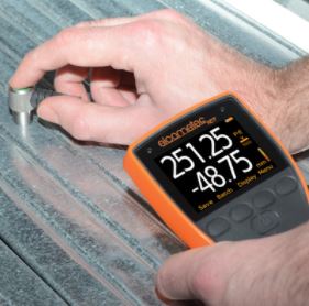
Using the Elcometer MTG8’s differential mode, which displays the last reading, and how much it differs from the user definable nominal value – also known as the target thickness – you get an instant indication of where the material is thicker or thinner than expected.
The Elcometer MTG8 also has B-Scan, which shows any changes in the material thickness, visually, as you move across the surface – ideal for quickly identifying large changes in depth within the material.
What’s more, the Elcometer MTG8’s ability to set high and low limits, means that whenever a reading exceeds the range, the gauge gives you an audio and visual warning, clearly highlighting any problem areas, instantly.
The Elcometer MTG range have several calibration options; with simple, on-screen instructions that guide you through each method – so it’s easy to maintain the gauge’s accuracy, at all times. To find out more about all of the calibration methods, make sure you watch our Ultrasonic NDT calibration videos.
The Elcometer MTG8 also allows you to programme up to 3 calibration memories, so you can select a saved calibration method without the need to re-calibrate the gauge.